Calculating cable pulling tensions
By Steve Eckardt, Product Engineer
SUPERIOR ESSEX
Member of NEMA, ICEA
Table of contents
Preface
Maximum pulling tension on a cable
Maximum permissible pulling length
Cable grip tension
Calculated pulling tension – straight section of conduit
Calculated pulling tension – curved (bent) section of conduit
Maximum sidewall pressure at bends
General guidelines for cable pulling
The following data is intended as a general guide to aid individuals with the installation of cables inside ducts, raceways or conduit. These recommendations are based upon a study sponsored by the ICEA (Insulated Cable Engineers Association). The information contained herein is not a comprehensive set of instructions. An engineer or technician experienced with installations should be consulted for particular applications where out-of-the-ordinary conditions exist or could be encountered.
Preface (Back to top)
Before installing cables, it is recommended that the routing be thoroughly inspected to avoid bends and/or pulling tensions that exceed specified limits. Good design of the duct, raceway or conduit itself along with the routing is essential to ensure damage-free installation and the full service life of all components.
Maximum pulling tension on a cable (Back to top)
For cable equipped with pulling eye or pulling bolt, the formula shown below is used to calculate the maximum allowable pulling tension on the cable for the entire routing.
Tm = K x n x CMA (Formula 1)
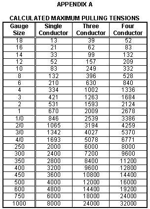
Where:Tm = maximum pulling tension (lbs.) (see Appendix A for calculated tensions)
K = constant
• 0.008 for copper conductors
• 0.006 for aluminum conductors
n = number of conductors
CMA = circular mil area for one conductor
Maximum permissible pulling length (Back to top)
The maximum length of cable that can safely be pulled through conduit is calculated as shown below.
Lm = Tm / ( W x f ) (Formula 2)
Where:Lm = maximum pulling length, feet
Tm = maximum pulling tension, lbs.
W = weight of cable, lbs./ft.
f = coefficient of friction (if unknown, use 0.5)
Cable grip tension (Back to top)
When cable grip is used over non lead-jacketed cable, the pulling tension should not exceed 1,000 lbs. or 1,000 lbs. per grip (when used with multi-conductor cables) and the tension calculated in Formula 1.
Calculated pulling tension – straight section of conduit (Back to top)
Ts = L x W x f (Formula 3)
Where:Ts = pulling tension at end of straight section, lbs.
L = length of straight section, feet
W = weight of cable, lbs./ft.
f = coefficient of friction (if unknown, use 0.5)
Calculated pulling tension – curved (bent) section of conduit (Back to top)
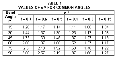
Tb = Ts x efa (Formula 4)
Where:Tb = pulling tension at end of bend, lbs.
Ts = pulling tension at end of straight section entering the bend, lbs.
e = naperian log base (2.718)
f = coefficient of friction (if unknown, use 0.5)
a = angle of bend (radians)
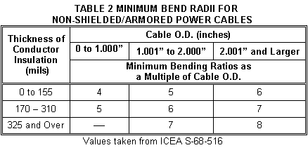
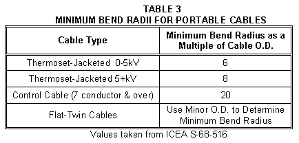
(See Table 1 with efa values for common angles and Tables 2 & 3 for minimum bend radii)
Maximum sidewall pressure at bends (Back to top)
Sidewall pressure is caused by the tension in the cable acting horizontally and the weight of the cable acting vertically. Generally, the tension of a cable immediately as it leaves a bend must not be greater than 300 times the bend radius (in feet), and the maximum sidewall pressure must not exceed 300 lbs./ft. Shown below are formulas to calculate the maximum allowable tension at a bend and the actual sidewall pressure.
Tbm = 300 x r (Formula 5)
Where:Tbm = maximum allowable pulling tension at bend, lbs.
r = bend radius, feet
P = Tb / r (Formula 6)
Where:P = actual sidewall pressure on cable, lbs./ft.
Tb = pulling tension at and of bend, lbs.
r = bend radius, feet
The maximum allowable pulling tension at bend (Tbm) is the limit that the calculated pulling tension (Tb) should be compared. If Tb is greater than Tbm, the possibility of redesign or re-routing should be considered.
Example – 1/0 AWG THHN, cable weight = 0.37 lbs./ft.
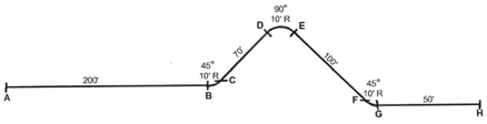
MAXIMUM PULLING TENSION, Tm
- Tm = .008 x 1 x 105600 = 846 lbs.
MAXIMUM PERMISSIBLE PULLING LENGTH, Lm
- Lm = 845 / (.37 x 0.5) = 4,568 ft
PULLING FROM POINT "A"
- Tension @ A = Zero
Tension @ B (Ts1) = 200 x .37 x .5 = 37 lbs.
Tension @ C (Tb1) = 37 x 1.48 = 55 lbs. [ PB-C = 55 / 10 = 5.5 lbs./ft ]
Tension @ D (Ts2) = 55 + [70 x .37 x .5] = 68 lbs.
Tension @ E (Tb2) = 68 x 2.19 = 149 lbs. [ PD-E = 149 / 10 = 14.9 lbs./ft ]
Tension @ F (Ts3) = 149 + [100 x .37 x .5] = 168 lbs.
Tension @ G (Tb3) = 168 x 1.48 = 249 lbs. [ PF-G = 249 / 10 = 24.9 lbs./ft ]
Tension @ H (Ts4) = 249 + [50 x .37 x .5] = 258 lbs.
PULLING FROM POINT "H"
- Tension @ H = Zero
Tension @ G (Ts1) = 50 x .37 x .5 = 9 lbs.
Tension @ F (Tb1) = 9 x 1.48 = 13 lbs. [ PG-H = 13 / 10 = 1.3 lbs./ft ]
Tension @ E (Ts2) = 13 + [100 x .37 x .5] = 32 lbs.
Tension @ D (Tb2) = 32 x 2.19 = 70 lbs. [ PE-D = 70 / 10 = 7 lbs./ft ]
Tension @ C (Ts3) = 70 + [70 x .37 x .5] = 83 lbs.
Tension @ B (Tb3) = 83 x 1.48 = 123 lbs. [ PC-B = 123 / 10 = 12.3 lbs./ft ]
Tension @ A (Ts4) = 123 + [200 x .37 x .5] = 160 lbs.
Pulling from either direction will not result in the tension or sidewall pressure exceeding the limits (846 lbs. & 300 lbs./ft). However, pulling from point "H" will result in approximately 40% less tension being placed on the cable. Therefore, it is most desirable to pull from point "H".
General guidelines for cable pulling (Back to top)
PREPARATION:
- Establish the direction of the pull based on safe pulling tensions and sidewall pressure calculations.
- Select the correct size pulling eyes, bolts or grips.
- Locate feeder reels, spools, etc. such that the tension at the feeding end is minimized.
- Use pulling equipment that provides smooth speed control.
- Choose a pulling rope that has the required tensile strength.
- Before pulling, make sure the conduit is clean and free of dirt, water, scale, etc.
- For long and/or heavy pulls, pre-lubricate the conduit and pull rope, particularly when using PVC.
- Install a dynamometer.
- Apply pulling lubricant (compound) liberally during the installation.
- If possible, use two-way communication at both ends of the run, particularly on long runs.
- Accelerate slowly and smoothly to a constant pulling speed.
- Avoid letting the cable stop part way through the pull. The friction is greatly increased when re-starting a pull.
- Seal the ends of the installed cable to prevent moisture from getting inside the cable.
- High voltage testing is recommended before and after the installation.